DecoBatten® is a lightweight aluminium batten system designed for quick and easy installation. Available in a one-piece or two-piece ‘Quick Click’ system, it offers versatile solutions for a wide range of applications. The following installation guide outlines a range of installation techniques. If you require further assistance, please contact us.
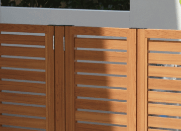
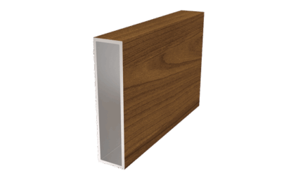
Personal Protective Equipment
Personal protective equipment (PPE) should be worn during installation. Processing the DecoBatten® in areas with excessive dust, sawdust, metal fines, and/or shavings risks potential damage to the finished surface.
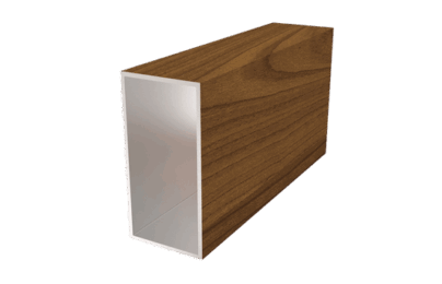
Installation Surface
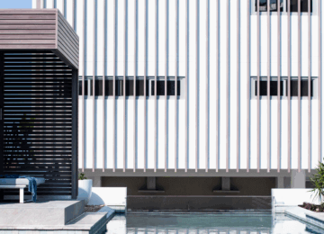
The installation surface should be clean and flat, and preparations (such as backing color) should be applied before the installation of DecoBatten® products.
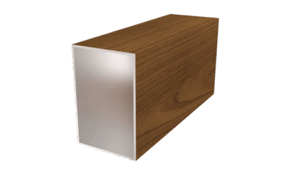
Supporting Structure and Fixings
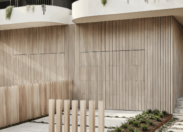
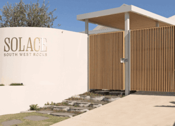
Before installation, the supporting structure should be assessed to ensure that it is structurally sound and able to support the live and dead loads of the DecoBatten® products to be installed. When fixing DecoBatten® products, it is recommended that they are fixed at a minimum of 600mm centers when applied to a solid backing or 450mm centers when applied to framing. However, due to the wide variety of installation applications, this may not be required for all cases. DECO recommends that users contact a certified engineer to assess the supporting structure and fixings required when installing DecoBatten®, especially in high-wind and high-risk areas.
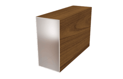
Important Information
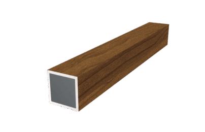
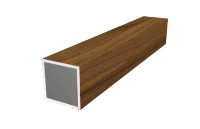
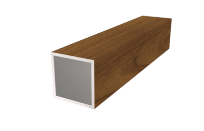
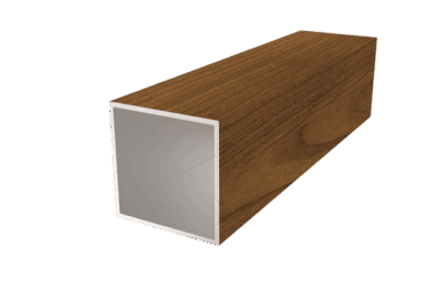
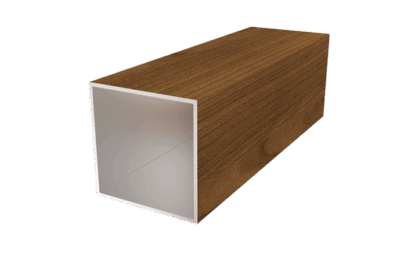
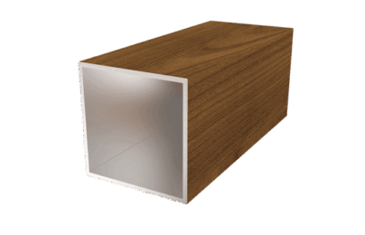
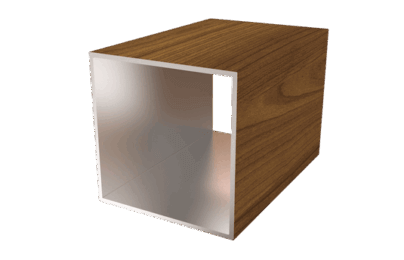
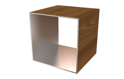
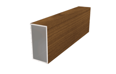
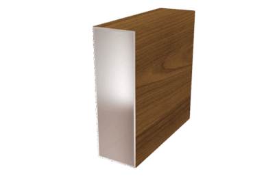
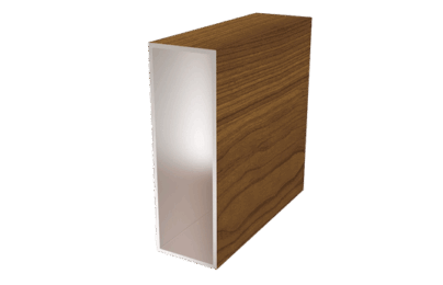
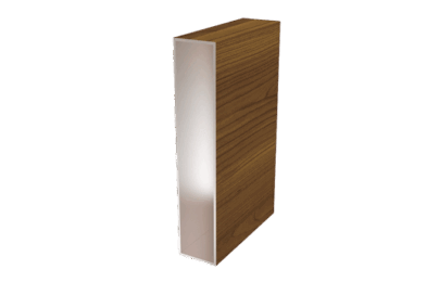
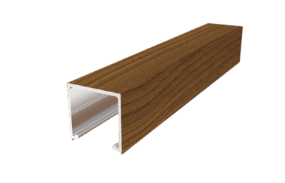
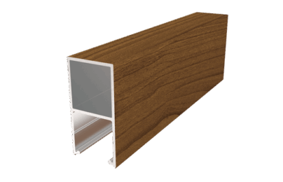
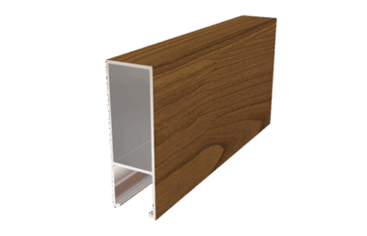
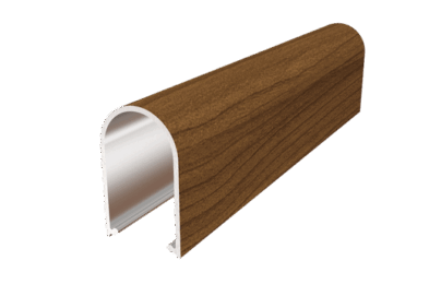
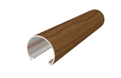
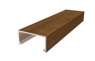
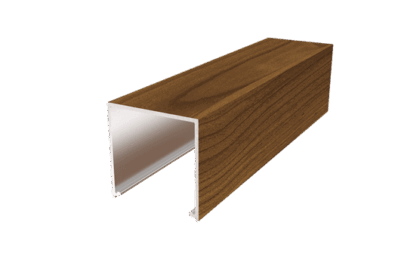
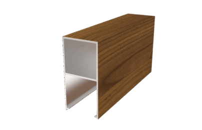
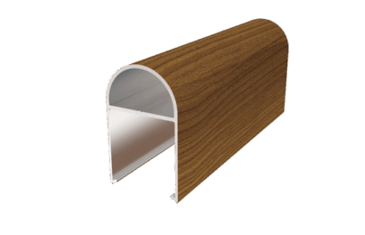
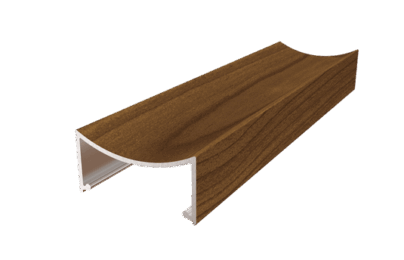
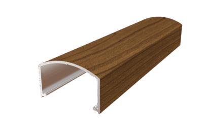
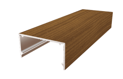
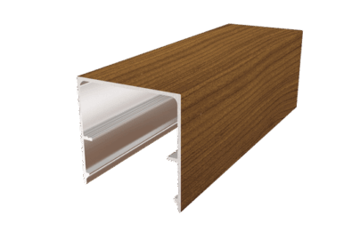
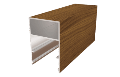
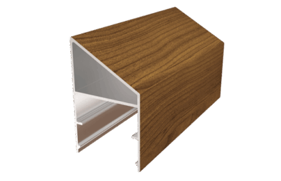
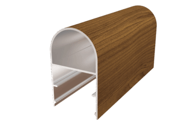
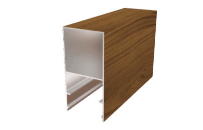
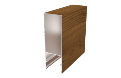
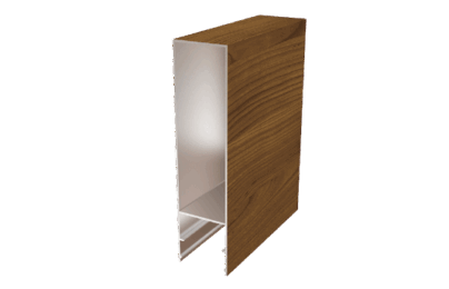
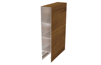
All DecoBatten® and accessories are supplied in 6.5m lengths. As part of the manufacturing process, the first 10mm of both ends of the extrusion are taped and not imaged, therefore each batten will need to be trimmed by 15mm on each end to remove the tape and provide a clean finish. After the removal of each end, the useable length is 6.45m.
25x25mm
32x32x2mm
40x40mm
50x50mm
65x65mm
100x100mm
150x150mm
25x50mm
25x100mm
40x80mm
50x75mm
50x100X1.6mm
50x150x2mm
50x150x3mm
50x200mm
50x250mm
25x25mm Cover
25x50mm Cover
25x75mm Cover
25x40mm Radius Cover
32x27mm Circular Cover
40x20mm Cover
40x40mm Cover
40x80mm Cover
40x65mm Radius Cover
40x20mm Concave Cover
40x25mm Convex Cover
50x25mm Cover
50x50mm Cover
50x75mm Cover
50x80mm Angle Cover
50x80mm Radius Cover
50x100mm Cover
50x150mm Cover
50x200mm Cover
50x250mm Cover
All testing has been done using the details provided in this installation guide. To claim the performances set out herein, the details in this guide must be followed.
AS1530.1
Methods for fire tests on building materials, components and structures – Combustibility test for materials.
AS 1530.3
Methods for fire tests on building materials, components and structures – Simultaneous determination of ignitability, flame propagation, heat release and smoke release.
AS 3837-G1
Method of test for heat and smoke release rates for materials and products using an oxygen consumption calorimeter.
NCC Compliant: Non-combustible
Volume 1 – Clause C.1.12 – Combustibility of Materials (No Amendment in NCC 2016).
Screws/Rivets
Metal – Colour matched pop rivets or self drilling TEK screws.
Wood – Self Drilling Timber Screws
Sealant/Adhesive
Deco recommends the use of high quality sealant and adhesives.
Impact Driver
A high-quality Impact Driver with an appropriate driver bit is recommended for fixing all extrusions to the building structure.
Mitre Saw
A high-quality Mitre Saw equipped with an aluminium cutting blade is recommended for cutting the boards to length and trimming the boardends.
Applications
Apply the Two-Piece Batten Base to the supporting structure and fix it as required.
If the batten is to be installed close to flush to an end surface, ensure at least 5mm of clearance is provided to allow the batten
cover to click over the base. To ensure a straight, consistent, and parallel installation, it is strongly recommended that a level be
used to position each base.
Centre Fixing
Fix with fasteners through the centre location groove.
Dual Fixing
Fix with fasteners at two appropriately spaced locations.
Install additional Two-Piece Bases and fix them as required.
To ensure equal and consistent spacing between each batten, space the bases according to your desired finished spacing using the following formula:
For 50mm Battens:
X (spacing between bases) = Desired finished spacing + 4mm
Y (centre-to-centre spacing) = Desired finished spacing + 50mm
For 40mm battens:
X (spacing between bases) = Desired finished spacing + 4mm
Y (centre to centre spacing) = Desired finished spacing + 40mm
For 25mm Battens
X (spacing between bases) = Desired finished spacing + 4mm
Y (centre-to-centre spacing) = Desired finished spacing + 25mm
Install additional Two-Piece Batten Covers and fix them as required.
Click the cover over each of the bases, ensuring a tight fit. Although the DecoBatten product is designed to ensure a secure click fit, if extra security against dislodgement is required, follow the detail provided below.
Adhesive Fix
Prior to installation, apply a bead of adhesive to the internal face of the step in the cover and click it over the base. Ensure that the cover is secured in place until the adhesive sets.
| Label | Description |
|---|---|
| A | Adhesive |
Mechanical Fix
Apply screws or rivets as required through the cover and into the base.
Apply the SpaceBase to the supporting structure and fix it as required.
If the batten is to be installed close to flush to an end surface, ensure at least 5mm of clearance is provided to allow the batten cover to click over the base. To ensure a straight, consistent and parallel installation, it is strongly recommended to use a level to position each base.
Centre Fixing
Fix with fasteners through the centre location groove.
Dual Fixing
Fix with fasteners at two appropriately spaced locations.
Install additional SpaceBases and fix them as required.
Detail A
Install additional Two-Piece Batten Covers and fix them as required.
Click the cover over each of the bases, ensuring a tight fit. Even though the DecoBatten product has been designed to ensure a secure click fit, if extra security against dislodgement is required, follow the detail provided below.
Adhesive Fix
Prior to installation, apply a bead of adhesive to the internal face of the step in the cover and click it over the base. Ensure that the cover is secured in place until the adhesive sets.
Mechanical Fix
Apply screws or rivets as required through the cover and into the base.
Double SpaceBase
Typically, we advise alternating left and right when screwing the double space base with 600mm spacing. However, in harsher environments a consistent and uniform fixing approach is recommended.
NOTE: The red dot indicates the location for screw or rivet placement.
Alternating Fixing
| Label | Description |
|---|---|
| A | 600mm (centres) |
| B | Screw/ Rivet |
Uniform Fixing
Triple SpaceBase
Typically, we advise changing the base for each screw with 600mm spacing However in harsher environments, a consistent and uniform fixing approach is recommended.
NOTE: The red dot indicates the location for screw or rivet placement.
Alternating Fixing
| Label | Description |
|---|---|
| A | 600mm (centres) |
| B | Screw/Rivet |
Uniform Fixing
Ripping SpaceBases
To adjust the length of your SpaceBases, measure where you want them to end and then use a table saw with a metal cutting blade to make a rip cut at that point.
| Label | Description |
|---|---|
| A | Trim Line |
| B | SpaceBases |
SpaceBase Post Ripping
Adhesive Secure
Apply high-quality adhesive to each of the legs as depicted and insert them into the One-Piece Batten. Take care to ensure that no adhesive is applied to the visible surface of the extrusion or endcap.
Ensure that the end cap is securely fastened in place until the adhesive sets.
One-Piece End Cap
Two-Piece End Cap
| Label | Description |
|---|---|
| A | Adhesive |
Mechanical Secure
Fix in place with mechanical fixings such as screws or rivets through the outside of the section into one or more of the internal legs.
DECO recommends using stainless steel, galvanised or aluminium fixings. Colour-matched rivets are available to order.
One-Piece End Cap
Two-Piece End Cap
Press Fit Aluminium End Caps
For all other profiles, press-fit aluminium end caps are available for both the One-Piece and Two-Piece batten systems. Depending on the profile, the end cap will be machined to fit snugly into the profile and can be secured using a high-quality adhesive.
One-Piece End Cap
Two-Piece End Cap
| Label | Description |
|---|---|
| A | Adhesive |
Two-Piece Batten End to End Concealed Fixing
Apply the fixing to the supporting structure and fix as required.
While applying fixings on the top, ensure they align with the bottom fixings.
| Label | Description |
|---|---|
| A | Fixing Bracket (35mm Maximum Width, 45mm Maximum Length) |
| B | Screw/ Rivet |
Elevation
Fix the Batten
Locate and fix the batten cover to the generic fixing at the top and bottom of the batten (see Details A and B).
Details A
Details B
Install the Two-Piece Batten bases and fix as required.
To ensure a straight, consistent and parallel installation, it is strongly recommended to use a level to position each batten. For a consistent finish, ensure the batten covers are spaced apart evenly during installation. We recommend using a batten or another solid item for even spacing.
One-Piece Batten End to End Fixing
End to End channel Fixing
| Label | Description |
|---|---|
| A | U Channel |
| B | U Channel |
| C | Screw/Rivet (Metal support structure - Pop Rivets or Self Drilling TEK Screws) |
End to End Angle Fixing
Front angle may be optional, based on the specific site requirements or construction detail. Check your engineer’s specifications.
| Label | Description |
|---|---|
| A | Angle |
| B | Screw/Rivet (Metal support structure - Pop Rivets or Self Drilling TEK screws) |
| C | Angle |
One-Piece Fixing Methods
| Label | Description |
|---|---|
| A | Screw/Rivet (Metal Support Structure - Pop Rivets or Self Drilling TEK screws) |
Back Fixing
The simpler method of fixing One-Piece battens is to fix through the back of the support material into the extrusion.
| Label | Description |
|---|---|
| A | Angle |
Fixed Surface Channel Fixing
| Label | Description |
|---|---|
| A | U Channel |
Bolt Fixing
Bolt fixing allows connection of materials at any angle or interval. Bolt fixing also allows on site construction of factory processed materials for a quick assembly and installation. When tightening bolts, ensure that they are not over-tightened as this may cause the extrusion to deform.
Flat Sheet Install
Exploded View
| Label | Description |
|---|---|
| A | Typical Framing Element |
| B | Moisture Barrier Layer / Sarking |
| C | 3mm Flat Sheet DecoPanel |
Finished Product
Channel Fix
Fix channel on supporting structure, using pop rivets or self-drilling TEK screws.
| Label | Description |
|---|---|
| A | One-Piece Batten Sleeve |
| B | Screw/Rivet |
| C | U Channel cut to size on site |
| D | Supporting structure |
Fix the batten on channel by fixing the batten through the adjacent faces of the batten, screwing into the inside channel.
| Label | Description |
|---|---|
| A | Screw/Rivet |
Plasterboard Fixing
Plasterboard screws are strongly recommended while installing 25mm Two-Piece battens onto a plasterboard backing. The countersunk heads of these screws provides a suitable grip to hold the battens in place against the plasterboard.
NOTE: Contact and discuss with your DECO representative for more information.
| Label | Description |
|---|---|
| A | Plasterboard |
- Position and pre-drill the base /SpaceBase
- Screw fix the base/SpaceBase with plasterboard screws
External & Internal Corner Details
External corner
Option 1
Position the batten along the edge of the wall and install it (refer to the diagram above). Use this batten as the base reference for placing and spacing the rest of the battens around this corner.
Option 2
Install a SpaceBase at the edge of the wall, allowing the batten to protrude by its width (see diagram below). Use SpaceBases for the remaining battens to ensure a consistent look.
| Label | Description |
|---|---|
| A | 50mm SpaceBase |
Internal Corner
Option 1
Position the batten along internal corner and install it (refer to the diagram below). Use this batten as the base reference for placing and spacing the rest of the battens around this corner.
Option 2
Position and install two battens with an equal distance between each batten and the internal corner (as shown in diagram below). Use these battens as the reference point for placing and spacing the remaining battens around this area.
NOTE: The spacing between each batten and the internal corner should be adjusted based on the size of the batten. Ensure the spacing is equal and adjust accordingly.