

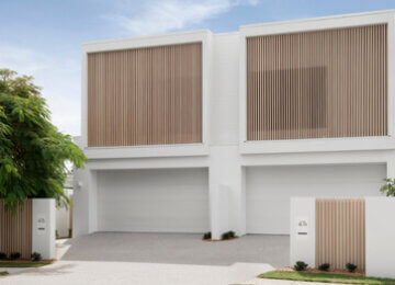


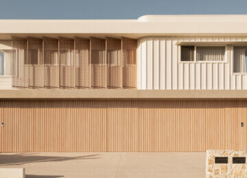
DecoPost™ Cover is our aluminium post wrap system that offers long-lasting durability for covering structural beams and posts. The following installation guide outlines a range of installation techniques. If you require further assistance, please contact us.
WARNING:
Care and Personal Protective Equipment (PPE) should be worn at all times when handling DecoPost™ products. Failure to do so risks potential serious injury, disablement or death. Simultaneously, ensure workspace is clean and free from dust, sawdust, metal fines and/or shavings. Processing of posts in areas with excessive dust, sawdust, metal dines and/or shavings risks potential damage to the finished surface.
Fixing Application Requirements
When fixing DecoPost™ to the wall, fixings should be used every 450mm for cyclonic applications or every 600mm for non-cyclonic applications. 30mm x 10G Self Tapping Panhead or Button Head screws (galvanised or stainless steel) shall be used in all circumstances.
Important Information
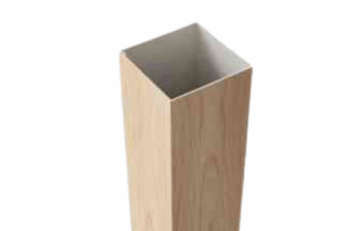
All DecoPost™ posts are supplied in 6.5m lengths. As part of the manufacturing process, the first 10mm of both ends of the extrusion are taped and not imaged, therefore each post will need to be trimmed by 15mm on each end to remove the tape and provide a clean finish. After the removal of each end, the useable length is 6.45m.
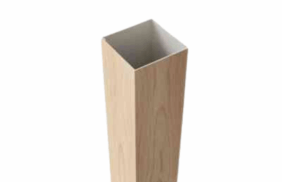
150x150mm
Post Trim
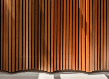
The Post Trim offers seamless edging around the top and bottom of the posts to hide any fixings or uneven surfaces. The Post Trim is our QuickClick batten system, available in 25mm, 40mm and 50mm widths for a variety of edging looks.
As part of DECO’s commitment to compliant building products, the DecoPost™ system has been designed to meet Australia’s stringent building standards. The DecoPost™ Cover been tested to and passed the following standards.
AS1530.1
Methods for fire tests on building materials, components and structures – Combustibility test for materials.
AS 1530.3
Methods for fire tests on building materials, components and structures – Simultaneous determination of ignitability, flame propagation, heat release and smoke release.
AS3837
Method of test for heat and smoke release rates for materials and products using an oxygen consumption calorimeter.
Screws/Rivets
Metal Support – Colour matched pop rivets or self
drilling TEK screws.
Wood Support – Counter sunk screws with stem.
Sealant/Adhesive
DECO recommends the use of high-quality sealant and adhesives.
Impact Driver
A high-quality Impact Driver with an appropriate driver bit is recommended for fixing all extrusions to the building structure.
Mitre Saw
A high-quality Mitre Saw equipped with an aluminium cutting blade is recommended for cutting the posts to length and trimming the ends.
Clamps
High-quality clamps with a minimum 130mm or 195mm span (depending on the size of the Post Cover) may be needed to assist in snapping the Post Cover together.
Doubled-sided Tape
A high-quality double-sided tape may be required to perform an adhesive fix.
Applications
1
Measure and Cut the Post Covers
Measure the distance between the floor and ceiling, then cut two Post Covers to the same length, subtracting 3mm to allow for fitment. Ensure the cross-section of the post is no larger than 90mm in both directions, if so, shave/sand/grind post down.
| Label | Description |
|---|---|
| A | This is the description for label A |
| B | This is the description for label B |
2
![]()

Cover Strip Setup
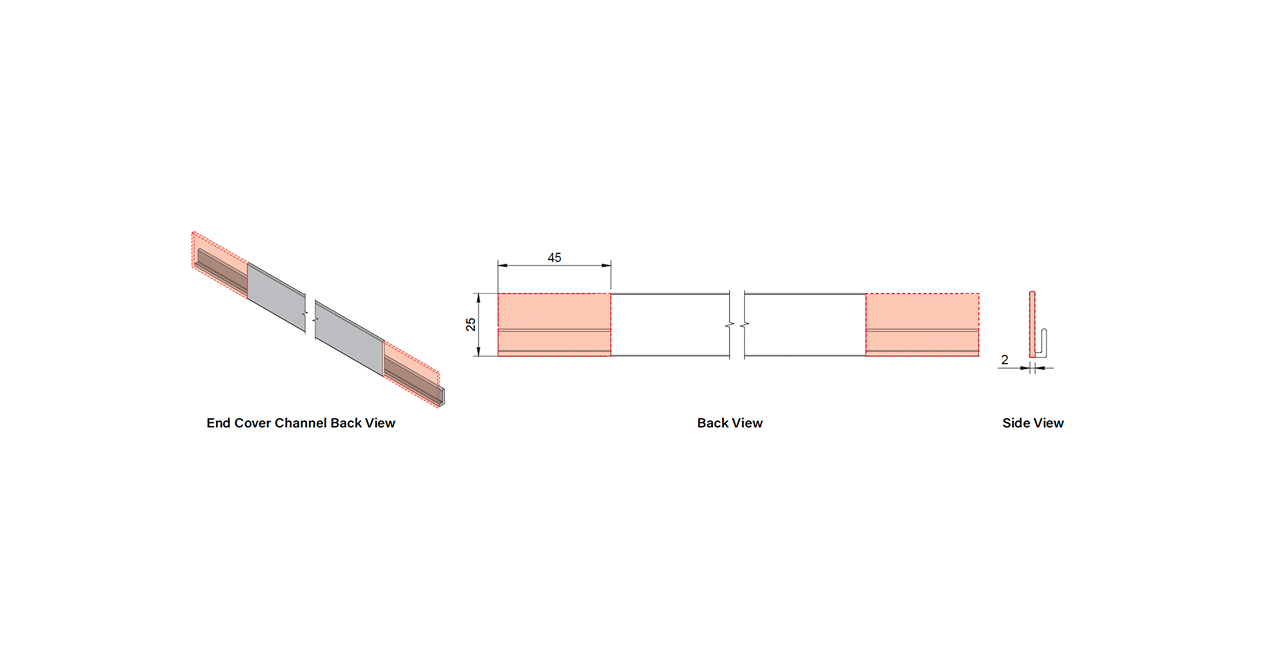
a) Install cladding accessories including End Cover Channels, 20×20 Angles, Joining Connectors, 20×20 Tee Sections and Internal or External Corners. When installing ensure all extrusions are fixed at maximum 600mm centres or as required for the applicable wind loads.
b) Measure and cut horizontal cladding accessories to length including Starter Strip and Cover Strip Base.
NOTE: DECO accessories are designed to be interchangeable, allowing you to customize them to fit your specific needs. The application demonstrated here represents a typical situation.
NOTCHING DETAIL FOR STARTER STRIP DC-CL07
Notching a starter strip is only necessary if the cladding is visible from the underside. Refer to the diagram below to notch the starter strip as illustrated, ensuring full coverage on the bottom face. NOTE: Areas highlighted red are to be notched.
1
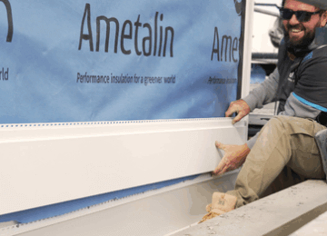
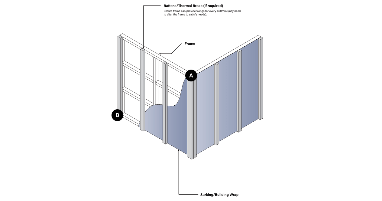
Apply Sarking or Building Wrap and Any Additional Battens or Noggins Required
When installing battens for a horizontal cladding facade, position the battens vertically with a spacing of 600mm between centres.
| Label | Description |
|---|---|
| A | This is the description for label A |
| B | This is the description for label B |
2
![]()
Cover Strip Setup
a) Install cladding accessories including End Cover Channels, 20×20 Angles, Joining Connectors, 20×20 Tee Sections and Internal or External Corners. When installing ensure all extrusions are fixed at maximum 600mm centres or as required for the applicable wind loads.
b) Measure and cut horizontal cladding accessories to length including Starter Strip and Cover Strip Base.
NOTE: DECO accessories are designed to be interchangeable, allowing you to customize them to fit your specific needs. The application demonstrated here represents a typical situation.
NOTCHING DETAIL FOR STARTER STRIP DC-CL07
Notching a starter strip is only necessary if the cladding is visible from the underside. Refer to the diagram below to notch the starter strip as illustrated, ensuring full coverage on the bottom face. NOTE: Areas highlighted red are to be notched.
3
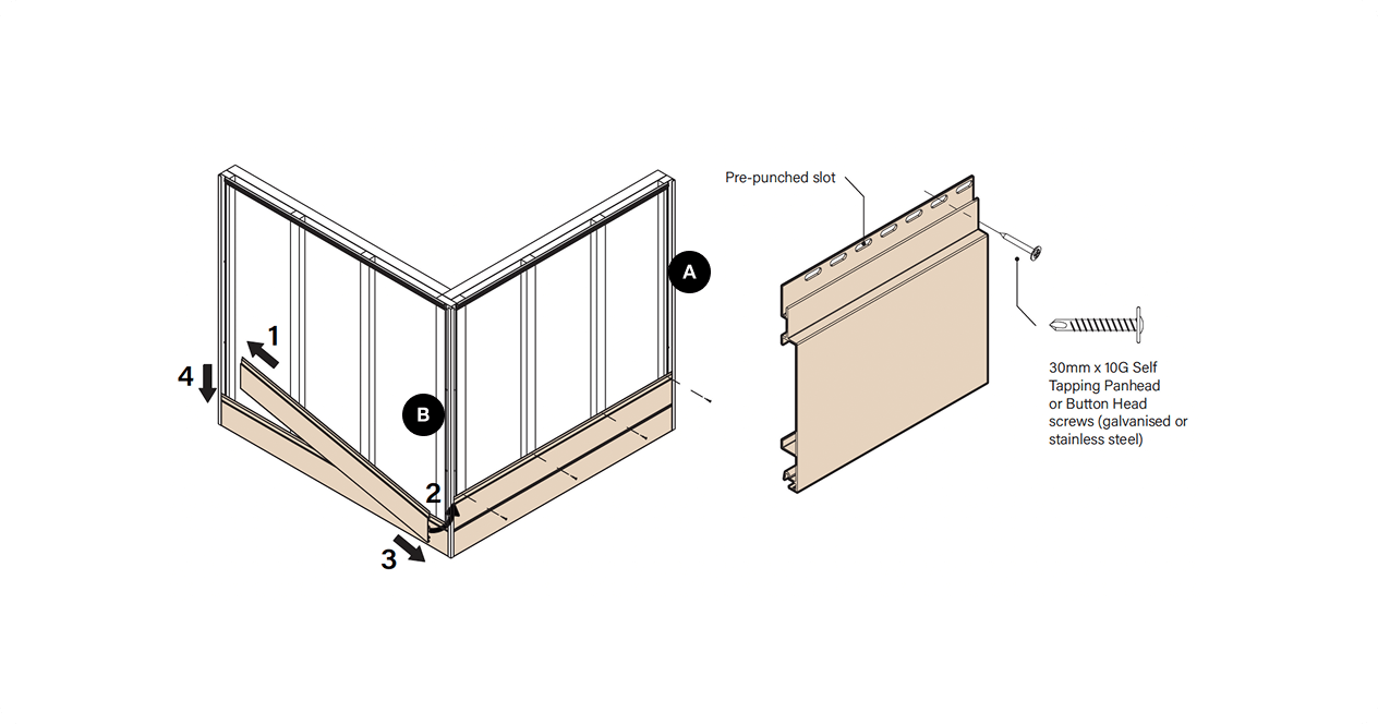
Install First Board
Measure, cut and install first board by positioning lip over the starter strip and fix board using 30mm 10G screws as required for your application. To ensure that the board has the required movement, the fixings are required to be installed through the pre-punched slots. Failure to do so may result in excessive stress and failure of the fixing.
CUTTING TIP
When cutting the boards to length, one method of ensuring that you have adequate coverage is to measure the distance available in the internal dimension of the End Cover Channel to the end of the cover at the other end and subtract 5mm. (See diagram)
4
Install Next Board and Repeat Until Final Board
Install the next board by positioning lip over the positioning leg on the previous board and fix board using 30mm 10G screws as required for the applicable wind loads. Ensure that the fixings are installed through the pre-punched slots.
TIP: After every 5th board, measure vertically from both ends of the cladding to ensure consistent length. Adjust the angle of the sixth board if needed for levelness, then proceed with fixing each subsequent board to maintain a level surface.
| Label | Description |
|---|---|
| A | This is the description for label A |
| B | This is the description for label B |
5
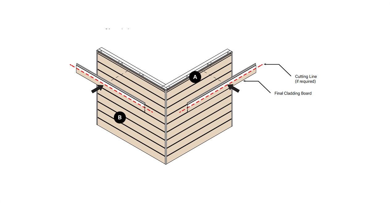
Rip and Install Final Board
The final cladding board might not be the right fit, so it needs to be ripped with a table saw. Measure the remaining space and cut the board accordingly for a proper fit.
| Label | Description |
|---|---|
| A | This is the description for label A |
| B | This is the description for label B |
6
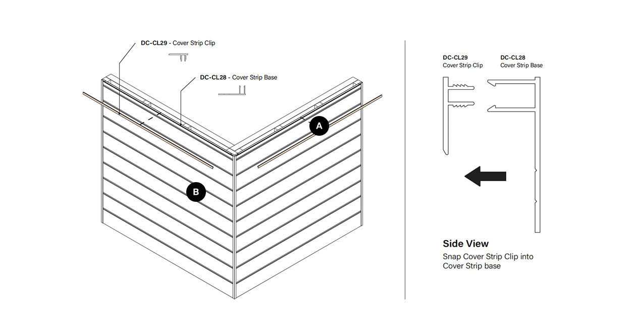
Cut and Install Cover Strips
Measure horizontal Cover Strip Clip between the external face of the vertical members (see cutting tip on previous page), cut to length and snap in to fit.
| Label | Description |
|---|---|
| A | This is the description for label A |
| B | This is the description for label B |
1
Apply Sarking or Building Wrap and Any Additional Battens or Noggins Required
When installing battens for a horizontal cladding facade, position the battens vertically with a spacing of 600mm between centres.
| Label | Description |
|---|---|
| A | This is the description for label A |
| B | This is the description for label B |