Visit the DECO Innovation Centre on our first open Saturday of 2026, February 14. Click to book an appointment.

DecoClad facade

Facades

A facade is both a visual statement and a functional shield—it defines a building’s character. Discover our range of cladding products suitable for facades.
Garage-door_banner_Dimah_2640 x 980

Garage Doors

Gone are the days of the simple roller door – today’s garage doors are integral to your home’s facade. Discover the products suitable for your perfect garage door look.
DecoCeiling aluminium ceiling - non-combustible

Ceilings & Soffits

Ceilings, soffits, and porticos enhance a building’s function, durability, and overall design. Find out which of our products is right for your project.
Banner_the-seaside-sanctuary-banner-2-1496-x-499-px.png

Fencing & Gates

Fencing and gates can transform your dream home. Find out which aluminium building products are right for your project.

Decking

Looking to create the perfect deck for your home? Discover our range of decking products.

Privacy Screening

Create the perfect privacy screening for your home. Find the right product to suit your project.

Pergola & Gazebos

Bring shade, structure, and architectural refinement to pergolas and gazebos with our range of aluminium building products.
aussie-coastal-reno_Banner_windows

Windows & Doors

Timber-look elegance, minus the upkeep. DecoWood® windows and doors combine lasting style with Super Durable™ performance.

Flooring

Looking to elevate your space? Look no further than DecoFloor® – the ultimate aluminium flooring solution.
Application_DECOSPLASH_Banner_IC-Edit
Splashbacks
DecoSplash® is a one-of-a-kind aluminium splashback system offering unmatched design flexibility for kitchens, bathrooms, and laundries.
DecoClad_carousel_V-Groove-Lorne

DecoClad®

Discover our beautiful and durable timber-look aluminium cladding system.
deco batten facade and screens

DecoBatten®

Achieve effortless architectural style with the cool, clean and contemporary lines of DecoBatten®.

DecoSlat®

Ease meets elegance with DecoSlat® fencing and screening systems.

DecoDeck®

Timber-look aluminium decking system designed for Australian conditions.
decopost pergola in a decwood curly birch finish with a skye background.

DecoPost™

Long-lasting timber-look aluminium posts for pergolas, alfrescos, and more.

DecoFloor®

Discover an effortless and innovative flooring solution with DecoFloor®.
CARD_DecoSign-Wineyard-Sign

DecoSign®

A durable and lightweight signage solution.
DecoSplash_Laundry_banner

DecoSplash®

A new kind of splashback for kitchens, bathrooms and laundries.
decobatten screening in decowood curly birch

Project Inspiration

Looking for ideas? Explore real spaces, smart solutions, and stunning real-life projects to spark your inspiration.

Where to See It

Use our interactive map to find a DECO display or reference site near you.
Finishes_Banner_IC-Batten Wall

Finish Selector

Our Finish Selector Tool allows you to browse and compare our full range of finishes.
installing decoclad

Find an Installer

Find a local tradesperson who can support you with your project and DECO product installation.

Create a Mood board

Visualise Your Space with Our Free Mood Board Tool
DecoClad_Banner_MAIN

DecoClad®

Discover our beautiful and durable non-combustible aluminium cladding system.
DecoBatten - the timber-look aluminium batten cladding system

DecoBatten®

Achieve effortless architectural style with the cool, clean and contemporary lines of DecoBatten®.

DecoSlat®

Ease meets elegance with DecoSlat® fencing and screening systems.

DecoDeck®

Timber-look aluminium decking system designed for Australian conditions.
decopost pergola in a decwood curly birch finish with a skye background.

DecoPost™

Long-lasting timber-look aluminium posts for pergolas, alfrescos, and more.

DecoFloor®

Discover an effortless and innovative flooring solution with DecoFloor®.
CARD_DecoSign-Wineyard-Sign

DecoSign®

A durable and lightweight signage solution.
DecoSplash_Laundry_banner

DecoSplash®

A new kind of splashback for kitchens, bathrooms and laundries.
DecoClad_Banner_MAIN

DecoClad®

Discover our beautiful and durable timber-look aluminium cladding system.
DecoBatten - the timber-look aluminium batten cladding system

DecoBatten®

Achieve effortless architectural style with the cool, clean and contemporary lines of DecoBatten®.

DecoSlat®

Ease meets elegance with DecoSlat® fencing and screening systems.

DecoDeck®

Timber-look aluminium decking system designed for Australian conditions.
decopost pergola in a decwood curly birch finish with a skye background.

DecoPost™

Long-lasting timber-look aluminium posts for pergolas, alfrescos, and more.

DecoFloor®

Discover an effortless and innovative flooring solution with DecoFloor®.
CARD_DecoSign-Wineyard-Sign

DecoSign®

A durable and lightweight signage solution.
DecoSplash_Laundry_banner

DecoSplash®

A new kind of splashback for kitchens, bathrooms and laundries.

DecoClad®
Install Guide

Enjoy the enduring beauty of DecoClad® in the bush, by the beach or in full sun. Effortless to install and maintain, DecoClad® is the ultimate in exterior cladding. The following installation guide outlines a range of installation techniques. If you require further assistance, please contact us.

DecoClad® is now certified to AS 1530.4 and FRL -/30/30 when following our FRL Installation Guide.

Download the FRL -/30/30 installation guide here.

WARNING: 

Care and Personal Protective Equipment (PPE) should be worn at all times when handling DecoClad® products. Failure to do so risks potential serious injury, disablement or death. Simultaneously, ensure workspace is clean and free from dust, sawdust, metal fines and/or shavings. Processing of cladding boards in areas with excessive dust, sawdust, metal dines and/or shavings risks potential damage to the finished surface.

Preparation:

To ensure a straight, consistent and parallel installation, it is strongly recommended that a level is used to position each cladding board throughout the installation.

Supporting Structure and Fixing: 

All framing should be constructed from steel or timber according to the requirements of the NCC and relevant standards to ensure resistance to wind loads, with studs positioned at maximum 600mm centres. For Non-Cyclonic vertical applications ensure that the wall is battened out or has studs at 600 centres; in Cyclonic applications studs should be installed at 450 centres. When using a Joining Connector for “Classic Installations”, or a Flushline Tee section for “Flushline Installations”, ensure that a stud, batten or noggin is installed behind the connector.

Fixing Application Requirements

When fixing DecoClad® to the wall, fixings should be used every 450mm for cyclonic applications or every 600mm for non-cyclonic applications. 30mm x 10G Self Tapping Panhead or Button Head screws (galvanised or stainless steel) shall be used in all circumstances.

Sarking/Building Wrap

To ensure a waterproof application, a sarking or building wrap layer should be installed first to prevent any water penetrating the building. Care should be taken to ensure that all penetrations are carefully sealed to ensure water does not penetrate the building wrap or sarking.

Important Information 
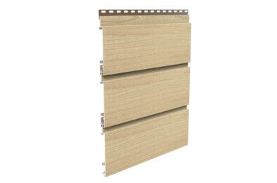
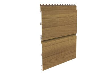
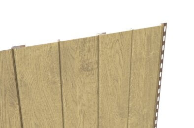
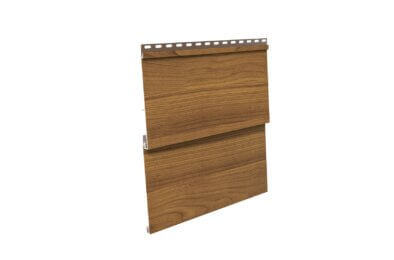
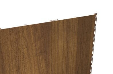
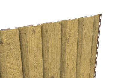
All DecoClad® and accessories are supplied in 6.5m lengths. As part of the manufacturing process, the first 10mm of both ends of the extrusion are taped and not imaged, therefore each cladding board will need to be trimmed by 15mm on each end to remove the tape and provide a clean finish. After the removal of each end, the useable length is 6.45m.


Narrowline_Curly Birch-Card

Narrowline

Shadowline_CoastalSG_Card

Shadowline

V-Groove_Linen Shore-Card

V-Groove

Weatherboard 160_Casuarina_Card

Weatherboard 160mm

Product-Seamline-Gallery-Kwila-Profile

Seamline™

DecoClad_Render-Castelline-Profile

Castelline™

Note: All accessories have been designed with detail in mind and provide a consistent 20mm depth profile (how far the accessories protrudes from the frame) and a 25mm external face.

CL07 - Starter Strip

The Starter Strip is the base profile which starts the connection to the wall. The Starter Strip is required to be attached to the wall at the bottom of horizontal applications, or to one side of vertical applications.

CL28 - Cover Strip Base

The Cover Strip Base is connected to the wall to allow the Cover Strip Clip (DCCL29) to be inserted and securely attached to the building.

CL29 - Cover Strip Clip

The Cover Strip Clip is a snap fit extrusion allowing a clean finish with no exposed fasteners.

CL23 - One-piece Internal Corner

The Internal Corner is designed to allow the easy application of cladding to corners pointing into the building used in “Classic Installation”.

CL32 - One-piece External Corner

The External Corner is designed to allow the easy application of cladding to corners pointing out from the building used in “Classic Installation”.

CL25 - End Cover Channel

The End Cover Channel can be installed to the sides to cover the cut ends of the extrusion in the “Classic Installation”.

CL24 - Joining Connector

The Joining Connector allows an easy connection of two full length cladding boards in wider applications or where a perpendicular feature is required in “Classic Installation”.

CL06 - Drainage Cover

The Drainage Cover can be installed above windows to ensure that any surface water is directed away from the top of the window system ensuring unwanted water does not access the top of the window system.

All testing has been done using the detail provided in this installation guide and in order to claim the performances set out here within, the detail in this guide must be followed.

AS1530.1

Methods for fire tests on building materials, components and structures – Combustibility test for materials.

AS 1530.3

Methods for fire tests on building materials, components and structures – Simultaneous determination of ignitability, flame propagation, heat release and smoke release.

AS 3837- G1

Method of test for heat and smoke release rates for materials and products using an oxygen consumption calorimeter.

NCC COMPLIANT – NON-COMBUSTIBLE

Volume 1 – Clause C.1.12 – Combustibility of Materials (No Amendment in NCC 2016).

AS 3715

Performance testing for thermoset powder coatings applied to aluminium intended for exterior architectural applications.

AS 4040.3

Methods of testing sheet roof and wall cladding – resistance to wind pressures for cyclone regions.

Screws/Rivets

Metal – Colour matched pop rivets or self drilling TEK screws.

Wood – Self Drilling Timber Screws

Sealant/Adhesive

Deco recommends the use of high quality sealant and adhesives.

Impact Driver

A high-quality Impact Driver with an appropriate driver bit is recommended for fixing all extrusions to the building structure.

Mitre Saw

A high-quality Mitre Saw equipped with an aluminium cutting blade is recommended for cutting the boards to length and trimming the boardends.

Table Saw

A high-quality Table Saw is recommended for ripping the final (top) board to the correct dimension for finishing of the installation.

Applications

1

Apply Sarking or Building Wrap and Any Additional Battens or Noggins Required

When installing battens for a horizontal cladding facade, position the battens vertically with a spacing of 600mm between centres.

Label Description
A Frame
B Battens/ Thermal Break (if required) Ensure frame can provide fixings for every 600mm (may need to alter the frame to satisfy needs).
C Sarking/ Building Wrap
2

Cover Strip Setup

a) Install cladding accessories including End Cover Channels, 20×20 Angles, Joining Connectors, 20×20 Tee Sections and Internal or External Corners. When installing ensure all extrusions are fixed at maximum 600mm centres or as required for the applicable wind loads.

b) Measure and cut horizontal cladding accessories to length including Starter Strip and Cover Strip Base.

NOTE: DECO accessories are designed to be interchangeable, allowing you to customize them to fit your specific needs. The application demonstrated here represents a typical situation.

Label Description
A DC-CL25-End Cover Channel
B DC-CL28-Cover Strip Base
C DC-CL07 - Starter Strip
D DC-CL32- External Corner


NOTCHING DETAIL FOR STARTER STRIP DC-CL07

Notching a starter strip is only necessary if the cladding is visible from the underside. Refer to the diagram below to notch the starter strip as illustrated, ensuring full coverage on the bottom face. NOTE: Areas highlighted red are to be notched.

3

Install First Board

Measure, cut and install first board by positioning lip over the starter strip and fix board using 30mm 10G screws as required for
your application. To ensure that the board has the required movement, the fixings are required to be installed through the pre-punched slots. Failure to do so may result in excessive stress and failure of the fixing.

Label Description
A Pre-punched slot
B 30mm x 10G Self Tapping Panhead or Button head screws (galvanised or stainless steel)


Cutting Tip

When cutting the boards to length, one method of ensuring that you have adequate coverage is to measure the distance available in the internal dimension of the End Cover Channel to the end of the cover at the other end and subtract 5mm. (See diagram)

Length of Board = x – 5mm
Length of Cover Strip = y – 2mm
4

Install Next Board and Repeat Until Final Board

Install the next board by positioning lip over the positioning leg on the previous board and fix board using 30mm 10G screws as required for the applicable wind loads. Ensure that the fixings are installed through the pre-punched slots.

TIP: After every 5th board, measure vertically from both ends of the cladding to ensure consistent length. Adjust the angle of the
sixth board if needed for levelness, then proceed with fixing each subsequent board to maintain a level surface.

Label Description
A Pre-punched slot
B 30mm x 10G Self Tapping Panhead or Button Head screws (galvanised or stainless steel)
5

Rip and Install Final Board

The final cladding board might not be the right fit, so it needs to be ripped with a table saw. Measure the remaining space and cut
the board accordingly for a proper fit.

Label Description
A Cutting Line (if required)
B Final Cladding Board
6

Cut and Install Cover Strips

Measure horizontal Cover Strip Clip between the external face of the vertical members (see cutting tip in Step 3), cut to
length and snap in to fit.

Label Description
A DC-C28 - Cover Strip Base
B DC-CL29 - Cover Strip Clip
Label Description
A DC-C28 - Cover Strip Base
B DC-CL29 - Cover Strip Clip
1

Apply Sarking or Building Wrap and Any Additional Battens or Noggins Required

When installing battens for a horizontal cladding facade, position the battens vertically with a spacing of 600mm between centres.

Label Description
A Frame
B Battens/ Thermal Break (if required) Ensure frame can provide fixings for every 600mm (may need to alter the frame to satisfy needs).
C Sarking/ Building Wrap
2

Cover Strip Setup

a) Install cladding accessories including End Cover Channels, 20×20 Angles, Joining Connectors, 20×20 Tee Sections and
Internal or External Corners. When installing ensure all extrusions are fixed at maximum 600mm centres or as required for the
applicable wind loads.
b) Measure and cut vertical cladding accessories to length including, Starter Strip and Cover Strip Base.

NOTE: DECO accessories are designed to be interchangeable, allowing you to customize them to fit your specific needs. The
application demonstrated here represents a typical situation.

Label Description
A DC-CL25-End Cover Channel
B DC-CL28-Cover Strip Base
C DC-CL25-End Cover Channel
D DC-CL32- External Corner

NOTCHING DETAIL FOR END COVER CHANNEL DC-CL25

When applying the End Cover Channel to the bottom edge of the cladding area, the rear wall will need to be notched (as seen in
Detail 3 and 4) in order to allow full coverage on the front face. Alternatively, the Cover Strip Base and Clip could be applied as
depicted in Detail 1 and 2 to the bottom edge. NOTE: Areas highlighted red are to be notched.

3

Install First Board

Measure, cut and install first board by positioning lip over the starter strip and fix board using 30mm 10G screws as required for your application. To ensure that the board has the required movement, the fixings are required to be installed through the pre-punched slots. Failure to do so may result in excessive stress and failure of the fixing. NOTE: DecoClad can be installed from either direction however Deco recommends working from the corner out.

Label Description
A Pre-punched slot
B 30mm x 10G Self Tapping Panhead or Button head screws (galvanised or stainless steel)


CUTTING TIP

When cutting the boards to length, one method of ensuring that you have adequate coverage is to measure the distance available in the internal dimension (x) of the End Cover Channel to the end of the cover strip base and subtract 5mm. (See diagram)

Length of Board = x – 5mm
Length of Cover Strip = y – 2mm
4

Install Next Board and Repeat Until Final Board

Install the next board by positioning lip over the positioning leg on the previous board and fix board using 30mm 10G screws as
required for the applicable wind loads. Ensure that the fixings are installed through the pre-punched slots.

TIP: After every 5th board, measure horizontally from both ends of the cladding to ensure consistent length. Adjust the angle of the
sixth board if needed for levelness, then proceed with fixing each subsequent board to maintain a level surface.

Label Description
A Pre-punched slot
B 30mm x 10G Self Tapping Panhead or Button head screws (galvanised or stainless steel)
5

Rip and Install Final Board

The final cladding board might not be the right fit, so it needs to be ripped with a table saw. Measure the remaining space and cut
the board accordingly for a proper fit.

Label Description
A Cutting Line (if required)
B Final Cladding Board
6

Cut and Install Cover Strips

Measure horizontal Cover Strip Clip between the external face of the vertical members (see cutting tip on previous page), cut to
length and snap in to fit.

Label Description
A DC-C28 - Cover Strip Base
B DC-CL29 - Cover Strip Clip
Label Description
A DC-C28 - Cover Strip Base
B DC-CL29 - Cover Strip Clip
1

Apply Sarking or Building Wrap and Any Additional Battens or Noggins Required

When installing battens for soffit cladding, position them perpendicular to the cladding’s direction with a spacing of 600mm centres (e.g., horizontal battens for vertical cladding).

Label Description
A Frame
B Battens/ Thermal Break (if required) Ensure frame can provide fixings for every 600mm (may need to alter the frame to satisfy needs).
C Sarking/ Building Wrap
2

Cover Strip Setup

a) Install cladding accessories including End Cover Channels, 20×20 Angles, Joining Connectors, 20×20 Tee Sections, Internal or External Corners. When installing ensure all extrusions are fixed at maximum 600mm centres or as required for the applicable wind loads.
b) Measure and cut cladding to length including, Starter strip and Cover Strip Base.

NOTE: DECO Accessories are designed to be interchangeable, allowing you to customize them to fit your specific needs. The application demonstrated here represents a typical situation.

Label Description
A DC-CL07 - Starter Strip
B DC-CL25-End Cover Channel
C DC-CL28-Cover Strip Base
D DC-CL28-Cover Strip Base
3

Install First Board

Measure, cut and install first board by positioning lip over the starter strip and fix board using 30mm 10G screws as required for your application. To ensure that the board has the required movement, the fixings are required to be installed through the pre-punched slots. Failure to do so may result in excessive stress and failure of the fixing.

NOTE: DecoClad can be installed from either direction however Deco recommends working from the corner out.

Label Description
A Pre-punched slots
B 30mm x 10G Self Tapping Panhead or Button head screws (galvanised or stainless steel)


CUTTING TIP

When cutting the boards to length, one method of ensuring that you have adequate coverage is to measure the distance available in the internal dimension of the End Cover Channel to the end of the cover at the other end and subtract 5mm. (See diagram)

Length of Board = x – 5mm
Length of Cover Strip = y – 2mm
4

Install Next Board and Repeat Until Final Board

Install the next board by positioning lip over the positioning leg on the previous board and fix board using 30mm 10G screws as required for the applicable wind loads. Ensure that the fixings are installed through the pre-punched slots.

TIP: After every 5th board, measure horizontally from both ends of the cladding to ensure consistent length. Adjust the angle of the sixth board if needed for levelness, then proceed with fixing each subsequent board to maintain a level surface.

Label Description
A Pre-punched slots
B 30mm x 10G Self Tapping Panhead or Button head screws (galvanised or stainless steel)
5

Rip and Install Final Board

The final cladding board might not be the right fit, so it needs to be ripped with a table saw. Measure the remaining space and cut the board accordingly for a proper fit.

Label Description
A Cutting Line (if required)
B Final Cladding Board
6

Cut and Install Cover Strips

Measure horizontal Cover Strip Clip between the external face of the vertical members (see cutting tip in Step 3), cut to length and snap in to fit.

Label Description
A DC-CL29 - Cover Strip Clip
B DC-C28 - Cover Strip Base
Label Description
A DC-C28 - Cover Strip Base
B DC-CL29 - Cover Strip Clip
1

Drainage Cover

It is strongly advised that all windows and doors installed using an inline application are installed with a drainage cover to the head (see below detail). Drainage Cover (DC-CL06) should be extended beyond the window opening by at least 60mm. In order to do so the Drainage Cover will need to be slotted to accommodate the DecoClad board. When installing, the End Cover Channel should be butted up to the Drainage Cover.


View of head and Jamb before installation of boards

Label Description
A Slot in Drainage Channel
B DC-CL25-End Cover Channel
C DC-CL06 Drainage Cover


View of Head and Jamb with DecoClad boards installed

Window Head – Return option overview

Window Head – Incline option overview

Window Jamb – Return option overview

Window Jamb – Incline option overview

2

Roof and Wall Junction/Parapet Flashing Detail


Roof and Wall Junction Overview

PLEASE NOTE: Details such as fixtures and sealant not shown.
Label Description
A Sarking/Building Wrap
B DecoClad Board
C Fix Drainage Cover Every 500mm
D Apron Flashing


Parapet Flashing Overview

PLEASE NOTE: Details such as fixtures and sealant not shown.

Label Description
A Custom Parapet Flashing min. fall of 10 degrees
B Flashing must overlap cladding
C Building Wrap/Sarking
3

Gable End Detail

Label Description
A DC-CL28 Cover Strip Base
B DC-CL07 Starter Strip
C DecoClad Board Cut to Angle
Label Description
D DC-CL29 Cover Strip Clip
4

Installing Cladding to an Uneven Wall

Install Top Hats/Packers to the Uneven Wall

Install Top Hats, in or out based on the circumstances.

Label Description
A Uneven Wall
B Top Hat (Packers may be required, ensure tophat is level)

Cover Strip Setup

a) Install cladding accessories including End Cover Channels, 20×20 Angles, Joining Connectors, 20×20 Tee Sections, Internal or External Corners. When installing ensure all extrusions are fixed at maximum 600mm centres or as required for the applicable wind loads. Refer to previous instructions to see how to do so.
b) Install cladding as usual, refer to previous instructions to see how to do so.

Label Description
A Cover Strip Setup
B Top Hat (Packers may be required, ensure tophat is level)