


Nam nulla vestibulum massa maecenas nisl. Fermentum blandit amet ultrices arcu. Blandit hendrerit feugiat lectus consequat ut fames arcu massa. Penatibus nibh massa est viverra amet tincidunt turpis consequat sem. Massa sollicitudin amet amet volutpat porttitor viverra tortor. Eget facilisis laoreet posuere in donec nunc et. Ac dui fringilla venenatis eleifend nullam id. Dui dignissim cursus dictum massa id at odio nisl leo. Nunc libero mauris ipsum vitae lacus viverra lectus eu.
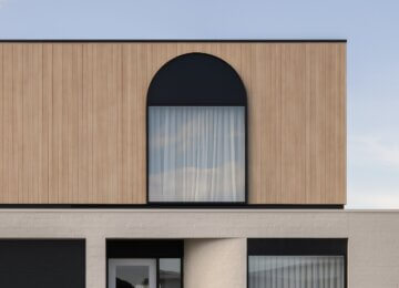
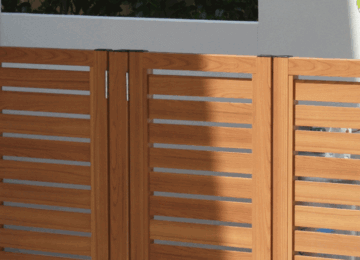
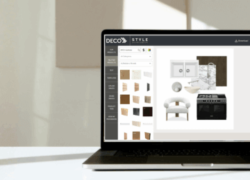
DecoClad® Boards
All DecoClad boards and accessories are supplied in 6.5m lengths. As part of the manufacturing process, the first 10mm of both ends of the extrusion are taped and not imaged, therefore each board will need to be trimmed by 15mm on each end to remove the tape and provide a clean finish. After the removal of each end, the useable length of each length is 6.47m. Accessories are available for two distinct finish options, “Classic Installation” and “Flushline Installation”.
Framing
All framing should be constructed from steel or timber according to the requirements of the NCC and relevant standards to ensure resistance to wind loads, with studs positioned at maximum 600mm centres. For Non-Cyclonic vertical applications ensure that the wall is battened out or has studs at 600 centres; in Cyclonic applications studs should be installed at 450 centres. When using a Joining Connector for “Classic Installations”, or a Flushline Tee section for “Flushline Installations”, ensure that a stud, batten or noggin is installed behind the connector.
Fixing Application Requirements
When fixing DecoClad to the wall, fixings should be used every 450mm for cyclonic applications or every 600mm for non-cyclonic applications. 30mm x 10G Self Tapping Panhead or Button Head screws (galvanised or stainless steel) shall be used in all circumstances.
Sarking/Building Wrap
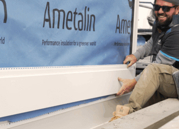
To ensure a waterproof application, a sarking or building wrap layer should be installed first to prevent any water penetrating the building. Care should be taken to ensure that all penetrations are carefully sealed to ensure water does not penetrate the building wrap or sarking.
Handle With Caution
WARNING – When handling DecoClad care should be taken and appropriate Personal Protective Equipment should be worn at all times. Failure to do so risks potential serious injury, disablement or death. When processing Cladding Boards or Accessories, care should be taken to ensure that the work space is clean and free from dust, sawdust, metal fines and/or shavings. Processing of the cladding board in areas with excessive dust, sawdust, metal fines and/or shavings risks potential damage to the finished surface
Pre Punched Extrusions
In order for DecoClad to achieve the highest levels of performance and to enable a quick and easy install, many of the extrusions come with pre-punched fixing slots. The fixing slots are included in the following profiles:
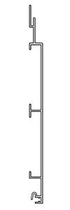
Note: All accessories have been designed with detail in mind and provide a consistent 20mm depth profile (how far the accessories protrudes from the frame) and a 25mm external face.
DC-CL07 – Starter Strip
The Starter Strip is the base profile which starts the connection to the wall. The Starter Strip is required to be attached to the wall at the bottom of horizontal applications, or to one side of vertical applications.
DC-CL28 – Cover Strip Base
The Cover Strip Base is connected to the wall to allow the Cover Strip Clip (DCCL29) to be inserted and securely attached to the building.
DC-CL29 – Cover Strip Clip
The Cover Strip Clip is a snap fit extrusion allowing a clean finish with no exposed fasteners.
DC-CL23 – Internal Corner
The Internal Corner is designed to allow the easy application of cladding to corners pointing into the building used in “Classic Installation”.
DC-CL32 – External Corner
The External Corner is designed to allow the easy application of cladding to corners pointing out from the building used in “Classic Installation”.
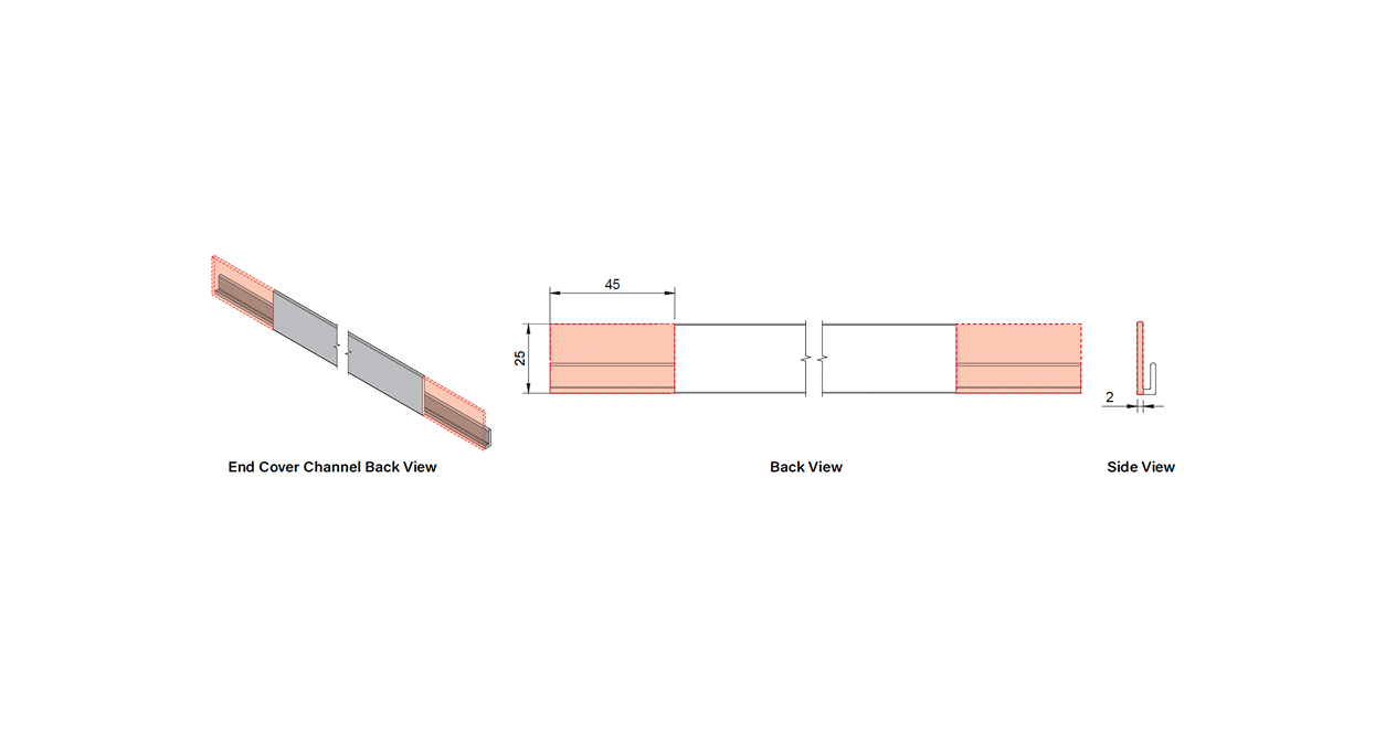
DC-CL25 – End Cover Channel
The End Cover Channel can be installed to the sides to cover the cut ends of the extrusion in the “Classic Installation”.
DC-CL24 – Joining Connector
The Joining Connector allows an easy connection of two full length cladding boards in wider applications or where a perpendicular feature is required in “Classic Installation”.
DC-CL06 – Drainage Cover
The Drainage Cover can be installed above windows to ensure that any surface water is directed away from the top of the window system ensuring unwanted water does not access the top of the window system.
DC-ANG2020 – Flushline 20X20 Anglet
For use in “Flushline Installation”, the 20mm x 20mm Angle is supplied in powder coated black or any powder coated finish you require. This extrusion is used to cover the ends of the cladding boards to create a clean finish.
DC-T2020 – Flushline Tee 20x20x1.6
The Flushline Tee section is used in “Flushline Installations” to replace the Joining Connector (DC-CL24) for a minimal look vertical or horizontal seam. Supplied in powder-coated black or other finishes on request.
Screws/Rivets
Metal – Colour matched pop rivets or self drilling TEK screws.
Wood – Self Drilling Timber Screws
Sealant/Adhesive
Deco recommends the use of high quality sealant and adhesives.
Impact Driver
A high-quality Impact Driver with an appropriate driver bit is recommended for fixing all extrusions to the building structure.
Mitre Saw
A high-quality Mitre Saw equipped with an aluminium cutting blade is recommended for cutting the boards to length and trimming the boardends.
Table Saw
A high-quality Table Saw is recommended for ripping the final (top) board to the correct dimension for finishing of the installation.
All testing has been done using the detail provided in this installation guide and in order to claim the performances set out here within, the detail in this guide must be followed.
AS1530.1
Methods for fire tests on building materials, components and structures – Combustibility test for materials.
AS/NZS1530.3
Methods for fire tests on building materials, components and structures – Simultaneous determination of ignitability, flame propagation, heat release and smoke release.
AS3837
Method of test for heat and smoke release rates for materials and products using an oxygen consumption calorimeter.
AS4040.3/AZUMA DESIGN
Resistance to wind pressures and cyclone regions
Installation Instructions
1

Apply Sarking or Building Wrap and Any Additional Battens or Noggins Required
When installing battens for a horizontal cladding facade, position the battens vertically with a spacing of 600mm between centres.
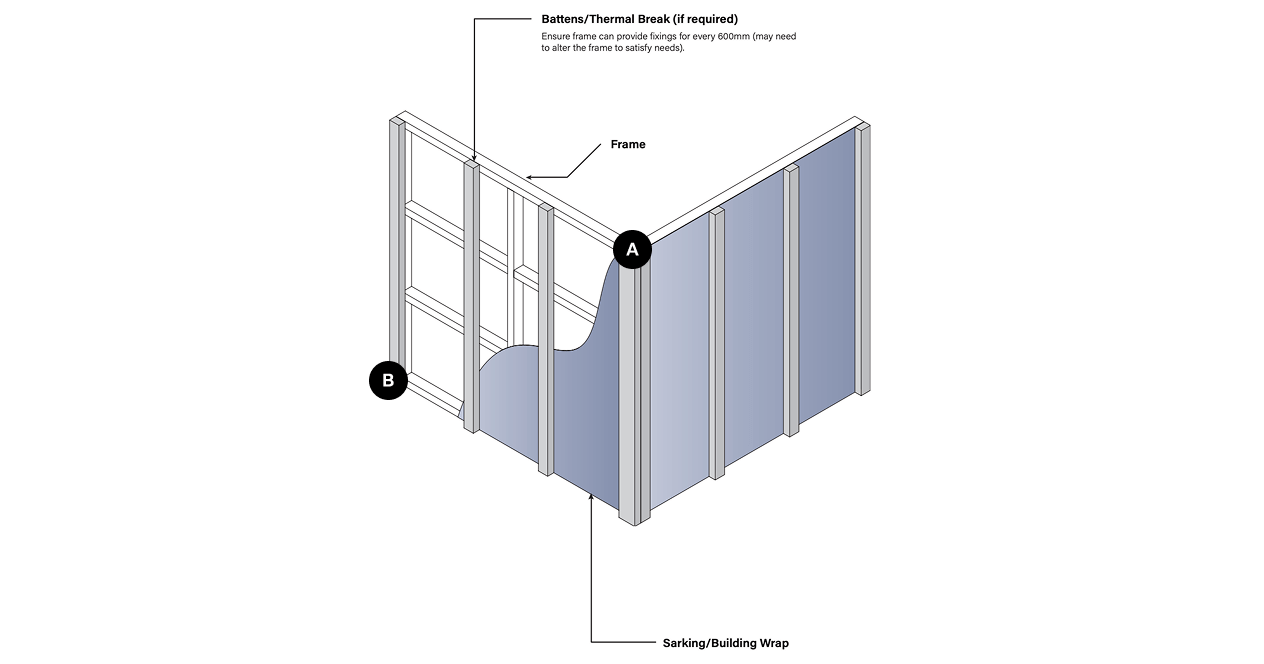
| Label | Description |
|---|---|
| A | This is the description for label A |
| B | This is the description for label B |
2
![]()
Cover Strip Setup
a) Install cladding accessories including End Cover Channels, 20×20 Angles, Joining Connectors, 20×20 Tee Sections and Internal or External Corners. When installing ensure all extrusions are fixed at maximum 600mm centres or as required for the applicable wind loads.
b) Measure and cut horizontal cladding accessories to length including Starter Strip and Cover Strip Base.
NOTE: DECO accessories are designed to be interchangeable, allowing you to customize them to fit your specific needs. The application demonstrated here represents a typical situation.
NOTCHING DETAIL FOR STARTER STRIP DC-CL07
Notching a starter strip is only necessary if the cladding is visible from the underside. Refer to the diagram below to notch the starter strip as illustrated, ensuring full coverage on the bottom face. NOTE: Areas highlighted red are to be notched.
1
Apply Sarking or Building Wrap and Any Additional Battens or Noggins Required
When installing battens for a horizontal cladding facade, position the battens vertically with a spacing of 600mm between centres.
| Label | Description |
|---|---|
| A | This is the description for label A |
| B | This is the description for label B |
2
![]()
Cover Strip Setup
a) Install cladding accessories including End Cover Channels, 20×20 Angles, Joining Connectors, 20×20 Tee Sections and Internal or External Corners. When installing ensure all extrusions are fixed at maximum 600mm centres or as required for the applicable wind loads.
b) Measure and cut horizontal cladding accessories to length including Starter Strip and Cover Strip Base.
NOTE: DECO accessories are designed to be interchangeable, allowing you to customize them to fit your specific needs. The application demonstrated here represents a typical situation.
NOTCHING DETAIL FOR STARTER STRIP DC-CL07
Notching a starter strip is only necessary if the cladding is visible from the underside. Refer to the diagram below to notch the starter strip as illustrated, ensuring full coverage on the bottom face. NOTE: Areas highlighted red are to be notched.
3
Install First Board
Measure, cut and install first board by positioning lip over the starter strip and fix board using 30mm 10G screws as required for your application. To ensure that the board has the required movement, the fixings are required to be installed through the pre-punched slots. Failure to do so may result in excessive stress and failure of the fixing.
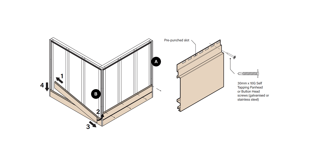
CUTTING TIP
When cutting the boards to length, one method of ensuring that you have adequate coverage is to measure the distance available in the internal dimension of the End Cover Channel to the end of the cover at the other end and subtract 5mm. (See diagram)
4
Install Next Board and Repeat Until Final Board
Install the next board by positioning lip over the positioning leg on the previous board and fix board using 30mm 10G screws as required for the applicable wind loads. Ensure that the fixings are installed through the pre-punched slots.
TIP: After every 5th board, measure vertically from both ends of the cladding to ensure consistent length. Adjust the angle of the sixth board if needed for levelness, then proceed with fixing each subsequent board to maintain a level surface.
| Label | Description |
|---|---|
| A | This is the description for label A |
| B | This is the description for label B |
5
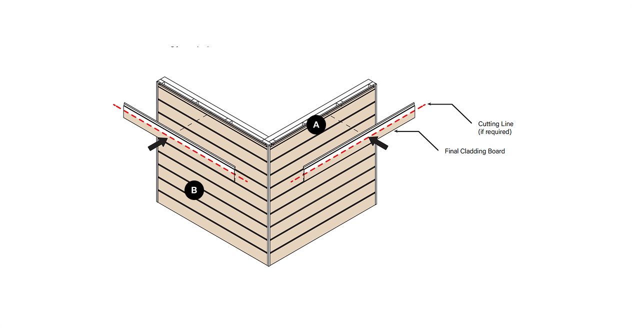
Rip and Install Final Board
The final cladding board might not be the right fit, so it needs to be ripped with a table saw. Measure the remaining space and cut the board accordingly for a proper fit.
| Label | Description |
|---|---|
| A | This is the description for label A |
| B | This is the description for label B |
6
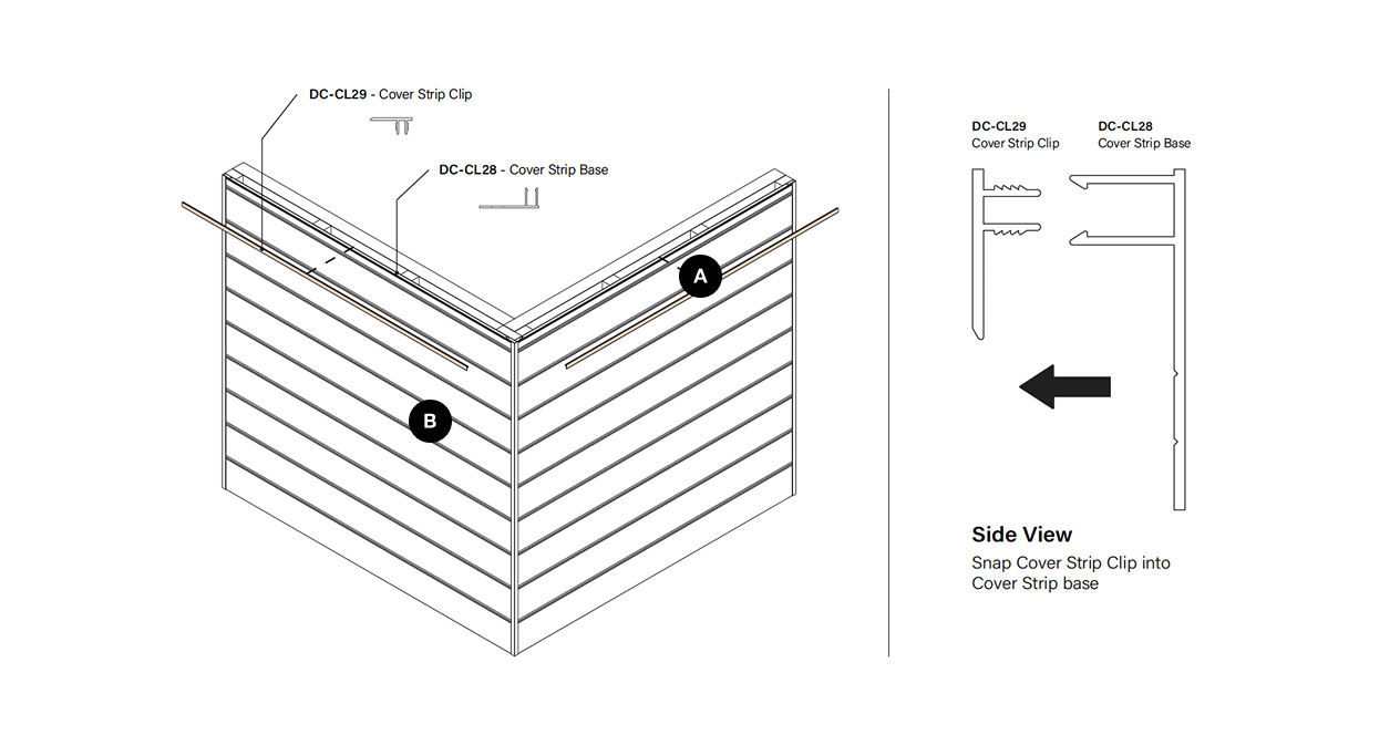
Cut and Install Cover Strips
Measure horizontal Cover Strip Clip between the external face of the vertical members (see cutting tip on previous page), cut to length and snap in to fit.
| Label | Description |
|---|---|
| A | This is the description for label A |
| B | This is the description for label B |
1
Apply Sarking or Building Wrap and Any Additional Battens or Noggins Required
When installing battens for a horizontal cladding facade, position the battens vertically with a spacing of 600mm between centres.
| Label | Description |
|---|---|
| A | This is the description for label A |
| B | This is the description for label B |