













DecoPost™ Cover is our aluminium post wrap system that offers long-lasting durability for covering structural beams and posts. The following installation guide outlines a range of installation techniques. If you require further assistance, please contact us.
WARNING:
Care and Personal Protective Equipment (PPE) should be worn at all times when handling DecoPost™ products. Failure to do so risks potential serious injury, disablement or death. Simultaneously, ensure workspace is clean and free from dust, sawdust, metal fines and/or shavings. Processing of posts in areas with excessive dust, sawdust, metal dines and/or shavings risks potential damage to the finished surface.
Installation Surface
For the best results, the DecoPost™ Cover should be installed onto clean, flat posts. If major imperfections exist, the post should be cleaned and
flattened before installation.
Supporting Structure
Before installation, assess the post for cracks, splits, or damage. Apply pressure to test for excessive flexibility and feel for soft spots indicating decay
or rot. DecoPost™ Cover is not designed as a structural member and the integrity of the post should be verified.
Important Information
All DecoPost™ posts are supplied in 6.5m lengths. As part of the manufacturing process, the first 10mm of both ends of the extrusion are taped and not imaged, therefore each post will need to be trimmed by 15mm on each end to remove the tape and provide a clean finish. After the removal of each end, the useable length is 6.45m.

As part of DECO’s commitment to compliant building products, the DecoPost™ system has been designed to meet Australia’s stringent building standards. The DecoPost™ Cover been tested to and passed the following standards.
AS1530.1
Methods for fire tests on building materials, components and structures – Combustibility test for materials.
AS 1530.3
Methods for fire tests on building materials, components and structures – Simultaneous determination of ignitability, flame propagation, heat release and smoke release.
AS3837
Method of test for heat and smoke release rates for materials and products using an oxygen consumption calorimeter.
Screws/Rivets
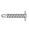
Metal Support – Colour matched pop rivets or self
drilling TEK screws.
Wood Support – Counter sunk screws with stem.
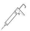
Sealant/Adhesive
DECO recommends the use of high-quality sealant and adhesives.
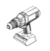
Impact Driver
A high-quality Impact Driver with an appropriate driver bit is recommended for fixing all extrusions to the building structure.
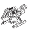
Mitre Saw
A high-quality Mitre Saw equipped with an aluminium cutting blade is recommended for cutting the posts to length and trimming the ends.
Clamps
High-quality clamps with a minimum 130mm or 195mm span (depending on the size of the Post Cover) may be needed to assist in snapping the Post Cover together.
Doubled-sided Tape
A high-quality double-sided tape may be required to perform an adhesive fix.
Applications
1

Measure and Cut the Post Covers
Measure the distance between the floor and ceiling, then cut two Post Covers to the same length, subtracting 3mm to allow for fitment. Ensure the cross-section of the post is no larger than 90mm in both directions, if so, shave/sand/grind post down.
| Label | Description |
|---|---|
| X | Length of Floor to Ceiling (3mm) |

2


Fix Post Cover – Adhesive Fix
Choose one face of the post (the face you wish to be flush with the Post Cover). Apply a strip of double-sided tape to the left and
right sides of that face. Now apply a high quality construction adhesive to the space between the two strips of tape. Wait until
adhesive sets before proceeding to the next step.


| Label | Description |
|---|---|
| A | Adhesive join |

| Label | Description |
|---|---|
| A | Adhesive Side |
| B | Snapping Features |
Apply the Post Cover to the face ensuring at least 3mm gap for snapping feature B.
Fix Post Cover – Mechanical Fix
Position one of the cut Post Cover pieces with an internal face flush with the face of the post you wish to fix through. Depending on
your post type use corresponding fixings below:
Metal post – colour-matched pop rivets or self drilling TEK screws.
Wood post – counter sunk screws with stem caps.

Starting at the top of the post, mechanically fix Post Cover, onto the post with one fixing.

Use a level to straighten Post Cover before putting second fixing in directly next to the first one (minimum 50mm gap, refer to diagram on the right).

Then fix Post Cover off at bottom. If you intend to install trim, ensure your fixings are no further than 10mm (centres) from the floor so that they will get covered.

Apply the Post Cover to the face ensuring at least 3mm gap for snapping feature B.
3


Snap on the Remaining Post Cover
Apply adhesive into the snapping feature of both Post Cover halves. Then snap the two halves of the Post Covers together. Clamps may be used to aid the snapping, ensuring the surface is protected from the clamp surfaces with rubber or timber.

| Label | Description |
|---|---|
| A | Rubber/Timber Protective Surface |
| B | (Optional) Hard Clamp 130mm Span |
Clamps may be used to aid the snapping. Use a mallet to lightly tap all areas to ensure that it is fully interlocked. To protect the finish, rubber or timber blocks should be used.

| Label | Description |
|---|---|
| A | Rubber/Timber Protective Surface |
| B | Adhesive |
After snapping the Post Cover together, secure in place with tape or clamps until the adhesive has fully set.

1


Apply ONE half of the Post Cover to the Supporting Structure and Fix as required
If the post is to be installed flush to an end surface, ensure at least 10mm of clearance are provided to allow the Post Cover to click over the Post Cover base. To ensure a straight, consistent and parallel installation, it is strongly recommended that a level is used to position each Post Cover base. Deco recommends 600mm centres when fastening Post Cover to its supporting structure.


Fix with fasteners at two appropriately spaced locations.
2


Install additional Post Cover Halves and Fix as Required

| Label | Description |
|---|---|
| X | (spacing between bases)= Desired finished spacing |

3


Install additional Post Cover Half and Fix as Required
Apply adhesive into the snapping feature of both Post Cover, then snap the two halves of the Post Cover together. A rubber mallet
may be used to snap the Post Cover in Post Cover base. Secure the Post Cover in place until the adhesive sets.


| Label | Description |
|---|---|
| A | Adhesive |
1

Internal Packing Details for an Undersized Post
To achieve structural integrity for your post, you can measure the gap between the post and the Post Cover, then fill this gap with packers as illustrated in the diagram below.

| Label | Description |
|---|---|
| A | Post |
| B | Packer |
1

NOTE: Deco’s QuickClick® batten system functions effectively as a colour-matched trim. While the diagrams in this section illustrate applications using a 25mm profile, the same methods apply to Deco’s 40mm and 50mm QuickClick® batten systems.
Measure and Cut Bases
Cut four bases to a length of 107mm each. Install these bases into the Post Cover, ensuring there is a 2mm gap between the bases and your ceiling or floor to allow the cover to snap in place.

| Label | Description |
|---|---|
| A | Screw/ Rivet |
| B | Base |
2


Measure and Cut Covers

| Label | Description |
|---|---|
| A | Colour-matched End Cap Thickness = 2mm |
| B | Length (mm) = 105 + (x) + (x) |
| X | 109mm |
End To End
Measure and cut two batten covers to a length of mm each and two batten covers to 105 + (x) + (x).
X = Width of the batten covers. (Refer to the diagram above)

3
| Label | Description |
|---|---|
| A | Length (mm) + 105 + (x) + (x) |
| X | Width of Batten Covers |
Measure and cut four lengths to 105 + (x) + (x).
X= Width of the batten covers. (Refer to the diagram above).
Using a mitre saw, cut a 45-degree angle on both ends of each length as shown in the diagram above.
4


Snap Covers into Base


| Label | Description |
|---|---|
| A | Ceiling |
| B | Post Trim |
| C | Post Cover |